

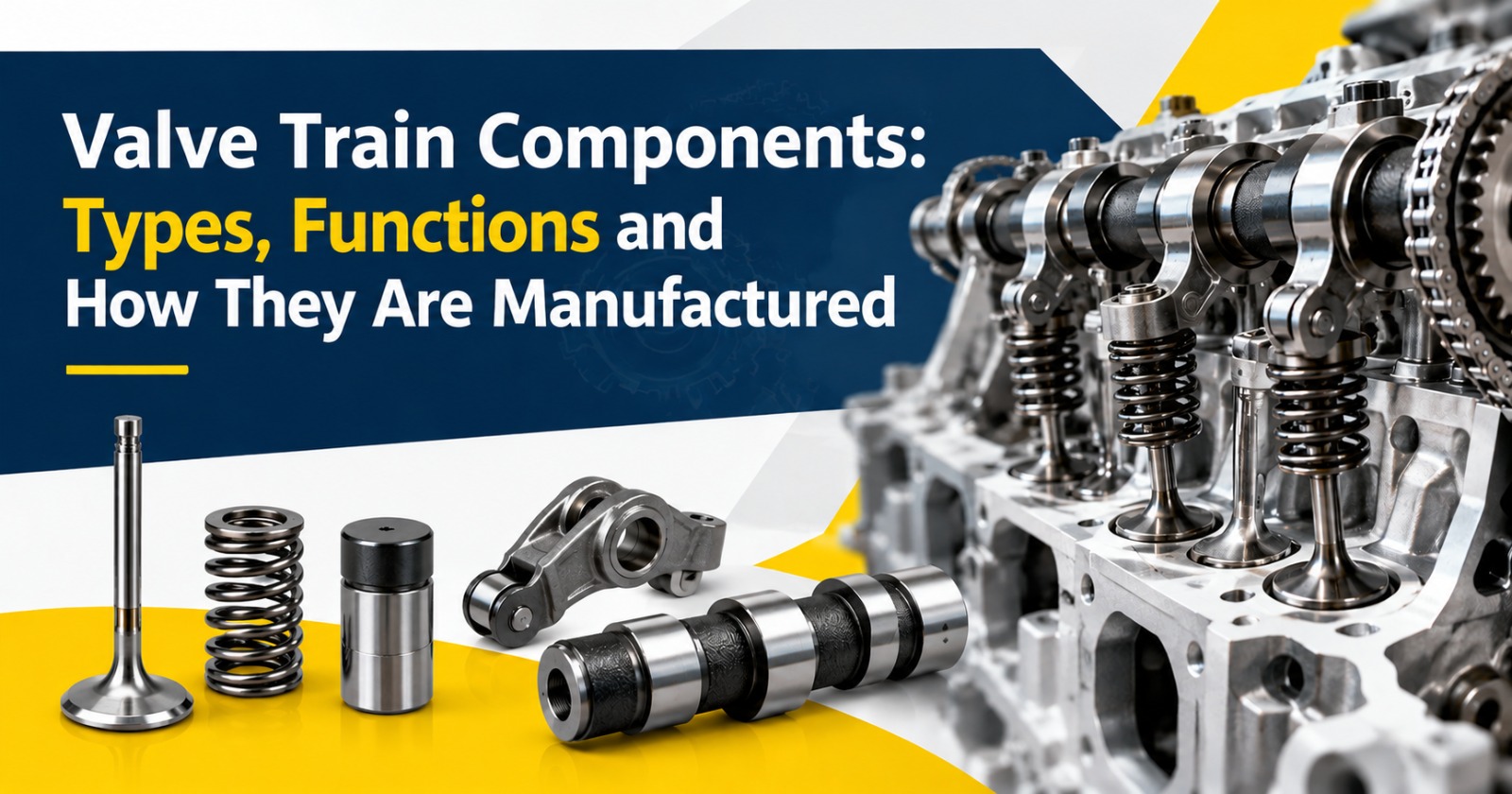
Valve train components carry motion from the camshaft to the engine valves. In an overhead valve engine the chain runs from the tappet through the push rod and rocker arm to the valve bridge or valve stem, and a spring closes the valve. Because each part passes load to the next, buyers should check material, heat treatment, dimensions and supplier documentation for the whole set, not for one part alone.
Valve train components are the parts that carry motion from the camshaft to the engine valves. Together they control when air enters the cylinder and when exhaust gas leaves it, in step with the crankshaft.
In heavy-duty engines these parts work for long hours under high loads. For that reason material choice, heat treatment and surface finish are specified closely on the drawing.
In an overhead valve engine the sequence is:
Because every part passes force to the next, a worn link affects the whole system. Engine builders therefore treat the parts as a matched set rather than as loose components.
| Component | Role in the Engine | Manufacturing Considerations |
|---|---|---|
| Tappet / valve lifter | Follows the cam lobe and starts the motion | Surface hardness, finish and dimensional accuracy |
| Push rod | Transfers motion from the tappet to the rocker arm | Straightness, end hardness and length |
| Rocker shaft assembly | Supports the rocker arms and guides their movement | Shaft diameter, straightness and oil hole position |
| Valve bridge | Lets one rocker arm open two valves together | Contact surface hardness and flatness |
| Valve spring | Closes the valve and keeps the train in contact | Spring load, free length and fatigue life |
Most valve train components use alloy or carbon steels that respond to heat treatment. Surfaces that touch moving parts are hardened to resist wear, while the core stays tougher to absorb shock.
Hardness, case depth and the heat-treatment method are defined on the drawing, and the supplier should be able to show records against them. Heat treatment can change size and shape slightly, so grinding and other finishing operations are planned around it.
The signs below are indications, not a diagnosis. Inspection is needed to confirm the cause.
| Sign | Possible Cause | Next Step |
|---|---|---|
| Ticking or tapping that rises with engine speed | Excess valve lash or worn contact surfaces | Check lash and inspect contact points |
| Rough idle or misfire in one cylinder | Bent push rod, stuck valve or worn rocker | Inspect that cylinder's valve train |
| Loss of power | Valve not opening fully | Inspect the whole chain for wear and bending |
| Rising fuel use with no other clear cause | Valve lift or timing affected by wear | Check lash and component wear |
In an overhead valve (OHV) engine the camshaft sits low in the block, so a push rod and rocker arm are needed to reach the valves. In an overhead cam (OHC) engine the camshaft sits in the cylinder head and acts on the valve more directly, so a push rod is not used.
Many heavy-duty diesel engines still use the OHV layout, which is why push rods, rocker shaft assemblies and tappets remain relevant for trucks, tractors and gensets.
Heavy-duty engines run longer hours at higher load and cylinder pressure, so their valve train parts generally use heavier sections, higher spring loads and more demanding surface hardness requirements than light-duty engines.
When defining requirements for a new engine, fix three inputs first: the duty cycle, the expected life between overhauls and the operating temperature. These guide material, heat treatment and finish.
| What to Check | What to Verify |
|---|---|
| Process route | Which of forging, machining, heat treatment and finishing are done in-house or outsourced |
| Drawing conformance | Dimensions, straightness and surface finish against the drawing |
| Material and heat treatment | Material certificate, hardness and case depth records where specified |
| Quality system | Applicable framework such as ISO 9001 or IATF 16949, with audit evidence |
| Sample approval | First-article report approved before volume supply |
| Traceability | Link from finished parts to material and process records |
Inspection scope depends on the component, drawing and control plan, so agree it with the supplier before the first order.
Ghaziabad Precision Products (GPP) was established in 1988 and operates five manufacturing facilities in Ghaziabad, Uttar Pradesh, with a combined footprint of approximately 37,500 sq. m. Its capabilities include forging, precision machining, heat treatment and finishing. The facilities page describes the equipment and processes in more detail. GPP supplies components to OEM and Tier-1 customers, and the clients page shows the sectors it serves.
GPP's range includes push rods, rocker shaft assemblies, valve bridges and tappets/valve lifters, which are manufactured to customer drawings and applicable specifications.
| GPP Capability | Buyer Benefit |
|---|---|
| Established in 1988 | A long operating history to review during supplier assessment |
| Five manufacturing facilities, approx. 37,500 sq. m. | A manufacturing network whose capacity can be discussed against your volume |
| Forging, precision machining, heat treatment and finishing | Several process stages available from one supplier, depending on the component |
| Tappets, push rods, rocker shaft assemblies, valve bridges | Several related valve train parts from a single manufacturer |
| Supplies OEM and Tier-1 customers | Experience with customer drawings and approval processes |
They are the parts that move the engine valves in step with the crankshaft. In an overhead valve engine the main ones are the tappet, push rod, rocker arm, rocker shaft, valve bridge, valve spring and the valve itself. Together they control when air enters the cylinder and when exhaust leaves.
In an overhead valve engine the push rod carries motion from the tappet to the rocker arm. It has to stay straight and stiff under repeated loading, with hardened ends that resist wear. Its length and end shape follow the engine drawing, because small changes affect valve timing.
A valve bridge lets one rocker arm open two valves at the same time in a four-valve cylinder head. It keeps both valves moving together. Its contact surfaces see repeated loading, so hardness, flatness and dimensions are specified on the drawing.
Life depends on lubrication, load, operating conditions and maintenance, so there is no single figure. Clean oil, correct valve lash and parts made to the engine drawing help them reach their intended service life. Follow the engine maker's overhaul intervals and wear limits.
Typical signs are ticking noise, misfiring, loss of power and higher fuel use. A failed or badly worn part can affect valve timing and, in serious cases, damage valves, pistons or the cylinder head. Inspect early when symptoms appear instead of waiting for the fault to spread.
Alloy steel and carbon steel are widely used, with spring steel for valve springs and cast materials for some parts. The grade and heat treatment depend on the load and wear conditions. Contact surfaces are usually hardened while the core stays tougher, as specified on the drawing.
Yes. Correct valve lash keeps valve timing accurate and limits noise and wear on contact surfaces. Check and set it at the interval and to the values given by the engine maker, and re-check after replacing valve train parts. Skipping this check lets small clearance errors grow.
A specialist understands how the parts work together and can discuss material, heat treatment and finishing in that context. It is easier to review process routes and records with a manufacturer that already makes related parts such as tappets, push rods and rocker shaft assemblies.
GPP supplies components to OEM and Tier-1 customers, and its range includes push rods, rocker shaft assemblies, valve bridges and tappets/valve lifters. Share your drawing, material grade and annual volume through the GPP contact page to discuss your requirement. Volumes and schedules are discussed per requirement.
Valve train components work as a chain, so the right questions cover the whole set: how each part is made, hardened, measured and documented. Match your sourcing checks to the drawing and control plan, and approve samples before volume supply.
To discuss a drawing or a new engine programme, send the drawing, material grade, annual volume and technical requirements through the contact page, or review the full product range first.